
A throughbolt, also called a wedge anchor or stud anchor, is a torque-controlled expansion anchor: a threaded stud with a cone at its embedded end, an expansion clip around the stud above the cone, and a washer and nut. Tightening the nut draws the cone into the clip, which presses against the drilled-hole wall, sets the anchor and clamps the fixture to the concrete.
Throughbolts are used for baseplates, brackets, railings and equipment supports. They are installed through the fixture, so the fixture can stay in position during drilling and setting.
Setting by tightening
The nut bears on the washer and fixture. As it is tightened, the stud and cone rise while the clip, held by friction at the hole wall, stays at the same depth. The cone forces the clip outwards and creates contact pressure against the concrete. Friction at this contact, together with local indentation of the concrete by the clip, transfers tension into the concrete.
The installation torque controls the expansion, which is why the throughbolt is classed as a torque-controlled expansion anchor.
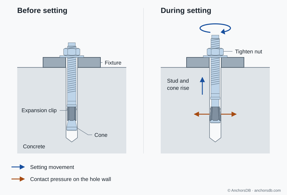
Figure 1. Throughbolt before and during setting.
Under increasing tension, the cone can be drawn further into the clip and expand it further. This follow-up expansion maintains contact pressure when the hole widens, for example when a crack opens. It depends on the clip continuing to grip the concrete while the cone moves.
Through-fixing and anchor length
In through-fixing, the anchor passes through a clearance hole in the fixture into the concrete, and the fixture serves as the drilling template. The fixture clearance hole and the concrete hole have separately specified diameters.
The anchor length must cover the fixture thickness, the embedment, the washer and nut, and the required thread projection. At the same embedment, a thicker fixture requires a longer anchor. Products with several assessed embedments give a maximum fixture thickness for each anchor length and embedment.
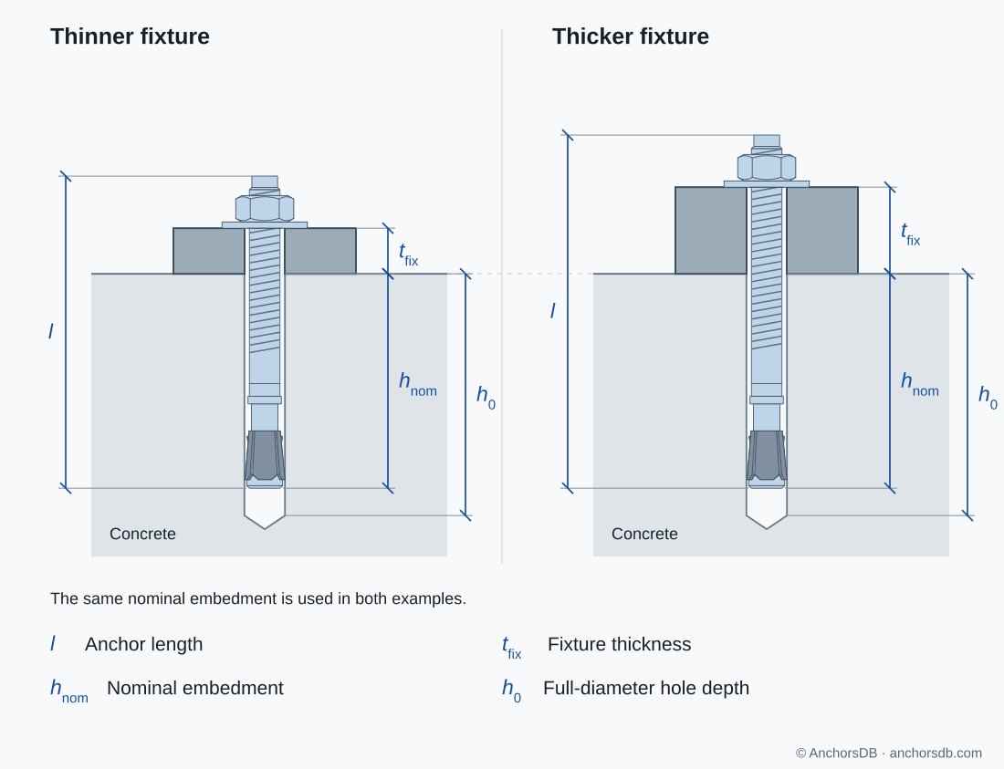
Figure 2. Anchor length for different fixture thicknesses.
Depth marks on the stud indicate the insertion depth but can be hidden by the fixture, so the setting position relative to the concrete surface must be established before insertion. The effective embedment used in design is defined by the product's anchorage geometry; see anchor dimensions and notation.
Cracked concrete and edge distance
A crack through the expansion zone widens the hole and reduces the contact pressure on the clip. Throughbolts assessed for cracked concrete maintain their anchorage through follow-up expansion; the European Technical Assessment (ETA) states which sizes and embedments qualify. See cracked vs uncracked concrete.
The expansion pressure also produces splitting forces in the concrete. Near an edge, between closely spaced anchors or in a thin member, these can split the concrete during setting. The minimum edge distance, spacing and member thickness in the ETA prevent this. A fastening that meets these minimum values can still have reduced concrete resistance in design; see how concrete strength and geometry affect anchor resistance.
Installation requirements
- Hole diameter: the clip needs the specified fit in the hole. An oversized hole can let the anchor turn or slip during tightening.
- Hole preparation: the drilling method and any cleaning form part of the installation specified in the ETA. Some products permit installation without separate cleaning under specified conditions.
- Hole depth and insertion: the hole must accommodate the setting depth. Drilling dust or a short hole can prevent the anchor reaching its intended position.
- Torque: the specified installation torque is applied with a calibrated torque wrench or an installation tool specified in the ETA. The nut needs clear access for the tool.
A stud that turns with the nut, or rises excessively before the specified torque is reached, indicates that the clip has not engaged. The installation is then not accepted until the hole, setting depth and anchor have been investigated.
A correctly set throughbolt can be loaded immediately.
Failure modes and resistance
Under tension, the resistance is limited by steel failure of the stud, pull-out or pull-through of the cone through the clip, concrete cone failure or splitting. The embedment and the surrounding concrete geometry determine which governs.
Under shear, the fixture bears on the stud. The resistance is limited by steel failure, concrete edge failure or concrete pry-out. Where the fixture stands off the concrete, shear also bends the stud across the gap; see tension, shear and combined loading.
Throughbolts are made in zinc-plated or galvanised carbon steel and in stainless steel. The material determines the permitted exposure and the steel resistance; see corrosion and anchor materials.
Removal
Removing the nut releases the fixture, but the expanded clip and stud remain in the concrete. Where a flush surface or later removal is required, this must be considered when the anchor is selected.