

The resistance of an anchor is limited by the lowest of several failure modes. Steel failure depends on the anchor alone. The concrete-related modes, namely concrete cone, pull-out, combined pull-out and concrete failure of bonded anchors, blow-out and splitting under tension, and concrete edge failure and pry-out under shear, depend on the concrete around the anchor: its strength and cracked or uncracked condition, the effective embedment, the edge distance, the spacing to neighbouring anchors and the member thickness. A published resistance therefore applies only to the concrete and geometry for which it was established.
Concrete strength and governing failure mode
Concrete-related resistances increase with concrete strength. For concrete cone failure, EN 1992-4 makes the basic resistance proportional to the square root of the characteristic cylinder strength: changing from C20/25 to C40/50 increases it by about 40 %. Steel resistance depends only on the anchor material and the stressed cross-section. Once steel failure governs, stronger concrete gives no further increase. Cracking reduces the concrete-related resistances; see cracked vs uncracked concrete.
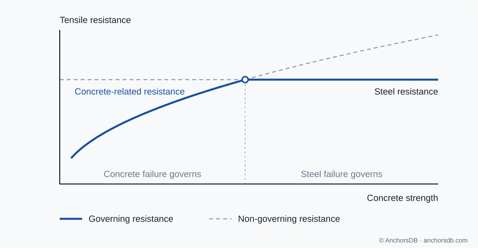
Figure 1. Schematic comparison: the lower of the two illustrated resistance limits governs. Only these two failure modes are shown.
Effective embedment and concrete breakout
Under tension, a concrete cone breaks out from the load-transfer zone of the anchor towards the concrete surface. Its basic resistance increases with the effective embedment to the power 1.5: doubling increases it by a factor of about 2.8. A deeper anchor can therefore move the governing mode from concrete cone to pull-out or steel failure, which do not increase with embedment in the same way. For a bonded anchor, a longer bonded length also increases the area through which bond transfers force into the concrete. The European Technical Assessment (ETA) states the permitted embedment range for each anchor size.
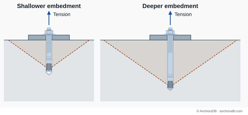
Figure 2. Deeper embedment can engage a larger breakout region. Concrete is shown in partial section and continues below the shaded field.
Edge distance and concrete breakout
Near a free edge, part of the concrete cone is missing, and the edge also disturbs the stress distribution in the remaining concrete. Under tension, both effects reduce the cone resistance when the edge distance is less than the characteristic edge distance . Its value is given in the ETA and is typically about . Under shear directed towards the edge, a half-cone of concrete can break out of the side face. Its resistance increases more than proportionally with edge distance, so it often limits shear resistance close to an edge. Moving an otherwise identical fastening towards an edge can therefore reduce its resistance and change its governing failure mode.
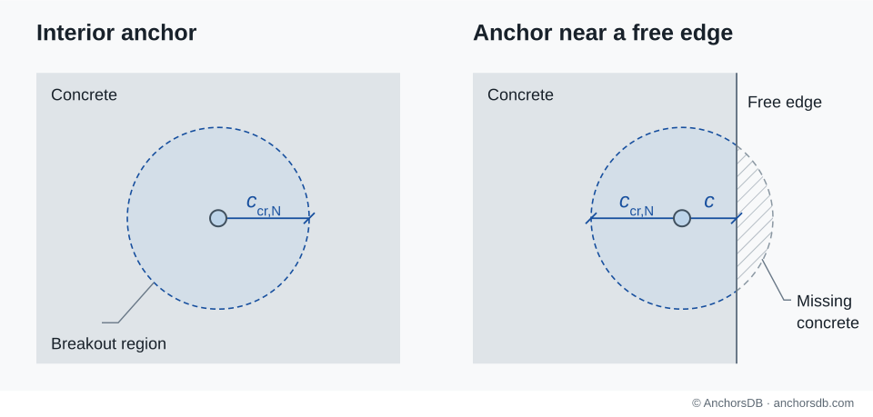
Figure 3. A free edge interrupts the tension-breakout region. The circles are schematic.
Anchor spacing and overlapping breakout regions
Under tension, anchors spaced at least the characteristic spacing , about , apart develop separate concrete cones. At smaller spacing the cones overlap and the anchors act on shared concrete, so the group resistance is less than the sum of the individual resistances. At very close spacing, two anchors provide little more concrete cone resistance than one. Adding anchors to a small baseplate therefore increases the steel resistance but may add little resistance against concrete failure.
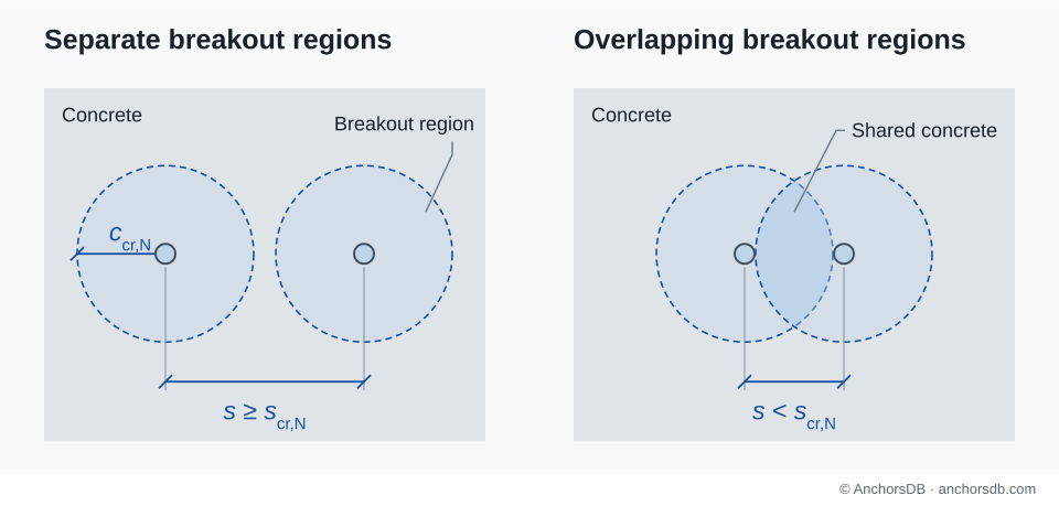
Figure 4. Separate and overlapping tension-breakout regions in plan. The circles are schematic.
Member thickness and splitting
Expansion forces from setting and the forces transferred under load act outwards from the anchor and produce splitting forces in the concrete. In a thin member, or close to edges, these can split the member. Splitting during installation is avoided by complying with the minimum member thickness, edge distance and spacing given in the ETA. Under load, EN 1992-4 requires splitting to be checked unless the edge distances are at least the characteristic edge distance for splitting, ( for groups), with the corresponding member thickness, or unless reinforcement resists the splitting forces and limits crack widths to 0.3 mm, with the resistances calculated for cracked concrete.
Minimum and characteristic distances
The minimum values , and are the closest geometry permitted by the ETA. They are often specified in combination: a smaller edge distance can require a larger spacing. Installation at a minimum value is permitted, but the resistance is reduced.
A characteristic distance is the distance beyond which a given failure mode receives no geometric reduction: for concrete cone failure and for splitting. Between the minimum and characteristic values, the resistance of each affected failure mode is reduced.
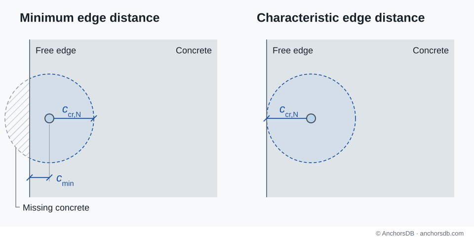
Figure 5. Minimum and characteristic edge distances for tension concrete breakout. The circles are schematic; permitted dimensions are given in the ETA.
See anchor dimensions and notation for the measurement references, and tension failure modes for the concrete failures behind these effects. For the resistance values used in a check, continue with characteristic, design and recommended loads.