

A heavy-duty sleeve anchor, often simply called a heavy-duty anchor, is a torque-controlled expansion anchor with a thick steel sleeve around a bolt or threaded rod and a separate expansion sleeve and cone at its embedded end. Tightening draws the cone into the expansion sleeve to set the anchor. The bolt or rod carries tension; the thick sleeve carries shear from the fixture into the concrete.
These anchors are used for steel baseplates, structural brackets and machinery. They are normally installed through the fixture, with the sleeve passing through the fixture hole into the concrete.
Setting by tightening
In a bolt-head version, the bolt passes through the sleeve and screws into the cone. In a projecting-thread version, a nut on the threaded rod bears on the washer. In both, tightening draws the cone towards the surface and forces the expansion sleeve against the hole wall. Friction at this contact, together with local indentation of the concrete, transfers tension into the concrete. The installation torque controls the expansion and clamps the fixture.
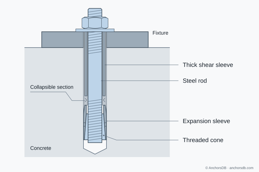
Figure 1. Projecting-thread sleeve anchor with a collapsible section.
Under increasing tension, the cone can be drawn further into the expansion sleeve. This follow-up expansion maintains contact pressure when the hole widens, for example when a crack opens.
Collapsible section and clamping
A collapsible section between the shear sleeve and the expansion sleeve shortens during tightening. It allows the fixture to be drawn down onto the concrete as the cone enters the expansion sleeve, so the shear sleeve does not act as a rigid spacer holding the fixture up. An anti-rotation feature on the expansion sleeve or collapsible section prevents the assembly turning with the bolt.
Shear transfer through the sleeve
Under shear, the fixture hole bears on the outside of the sleeve, which transfers the force into the concrete around the hole. The sleeve, and in bolt-head versions the bolt shank, provide the steel cross-section that resists shear. The assessed shear resistance therefore applies to the arrangement and fixture thickness for which it was established.
Concrete can still govern. Near an edge, shear towards the edge can cause concrete edge failure before the steel reaches its resistance, and a gap beneath the fixture introduces bending; see tension, shear and combined loading.
Hole size, anchor length and embedment
The drilled hole accommodates the outside of the sleeve, so the hole diameter is larger than the bolt thread. The bolt thread, the concrete hole diameter and the fixture hole diameter are specified separately, and the fixture hole must clear the sleeve.
The anchor length is chosen for the fixture thickness and the embedment. At the same embedment, a thicker fixture requires a longer anchor. For a given anchor length, a thinner fixture places more of the anchor below the surface, so the hole is drilled deeper than the depth quoted for the maximum fixture thickness, as stated in the installation data. Where several embedments are assessed, each has its own installation dimensions and resistance data; see anchor dimensions and notation.
Installation requirements
- Insertion depth: depth marks can be hidden by the fixture, so the setting position relative to the concrete surface is established before insertion.
- Hole preparation: the hole is drilled and cleaned as specified in the European Technical Assessment (ETA).
- Torque: the specified installation torque is applied with the stated tool. Tightening beyond the specified procedure draws the cone further into the expansion sleeve and changes the setting.
Rotation of the whole assembly, excessive movement or a fixture that does not seat indicates that the anchor has not set correctly; the installation is then investigated before it is accepted.
Cracked concrete, edges and special loading
Heavy-duty sleeve anchors are available with assessments for cracked concrete; the size, embedment and head version must be covered for the concrete condition at the anchor (see cracked vs uncracked concrete).
Expansion during setting produces splitting forces. The minimum edge distance, spacing and member thickness in the ETA prevent splitting during installation; the design then accounts for the actual edge distances and spacing (how concrete strength and geometry affect anchor resistance).
Seismic and fatigue assessments can add installation requirements, such as filling the clearance in the fixture hole.
Head versions and removal
Hexagon-head, projecting-thread and countersunk versions are available. A countersunk version requires a matching countersink and the assessed fixture dimensions. With a projecting-thread version, the fixture can be lifted off after the nut is removed while the expansion assembly stays set. With a bolt-head version, the bolt, washer and shear sleeve come out with the fixture, while the expansion sleeve and cone remain in the hole. Where removal or replacement is expected, the head version is chosen accordingly.