

Reinforced concrete is designed on the assumption that its tension zones crack. The reinforcement carries the tension across the cracks. An anchor installed in a tension zone must therefore be expected to lie in or close to a crack, and its resistance in cracked concrete is lower than in uncracked concrete.
EN 1992-4 leaves the determination of the concrete condition to the designer and notes that assuming cracked concrete is generally conservative. Uncracked concrete may only be assumed where it is verified for the service life of the fastening. The appearance of the concrete at installation does not establish its condition: a surface without visible cracks can crack later, and existing cracks can be closed at the time of inspection.
Formation of cracks in concrete members
Concrete has a low tensile strength. Cracks form where the tensile stress exceeds it, through:
- Bending: near midspan of a simply supported slab, the lower part of the section is in tension. In a continuous slab, the upper part is in tension over the internal supports and the lower part within the spans.
- Restraint: shrinkage and temperature changes produce tensile stresses where the structure prevents the concrete from moving freely, even without applied load.
- Direct tension: members such as ties crack across their whole section.
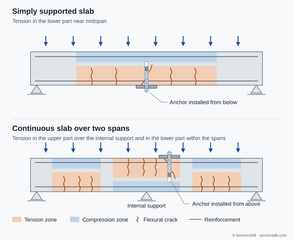
Figure 1. Tension zones and flexural cracks in a simply supported and a continuous slab. Shading marks where flexural tension is high enough to cause cracking. The anchors lie between reinforcing bars across the slab width; the overlap appears only in the side view.
Crack widths in reinforced concrete under quasi-permanent loads typically do not exceed about 0.3–0.4 mm. Under the maximum service loads they can reach about 0.5–0.6 mm. Cracks open and close as loads and temperatures change during service.
Cracks at anchor locations
A crack that forms near an anchor is likely to pass through the anchor location. The anchor itself raises the tensile stress in the surrounding concrete through the hoop stresses from expansion or preload, the local stresses from the anchor load and the stress concentration at the drilled hole. In slab tests, flexural cracks generally followed the transverse reinforcement but deviated to pass through the anchor locations.
Moving an anchor to an area without visible cracks therefore does not avoid the cracked condition if the area lies in a tension zone.
Verification of uncracked concrete
Uncracked concrete may be assumed only if a serviceability calculation shows that the concrete remains uncracked over the full embedment depth of the anchor. EN 1992-4 expresses this as a stress check. The tensile stress from external loads, including the anchor loads, plus the stress from restrained shrinkage, temperature change or support settlement must not exceed an admissible value, recommended as zero. Unless the restraint stresses are analysed, they are taken as 3 N/mm². Slabs, walls and shells spanning in two directions must satisfy the check in both directions.
With the recommended admissible stress of zero and the default restraint stress, the external loads alone must therefore keep the concrete in compression of at least 3 N/mm² over the full embedment depth. Uncracked concrete can normally be demonstrated only in compression zones, or where a detailed analysis of restraint stresses justifies a lower value.
Effects of cracks on anchor resistance
A crack through the anchorage interrupts the tensile stress field in the concrete and changes the contact between the anchor and the hole wall. The effect depends on the failure mode and the load-transfer mechanism:
- Steel failure: unaffected, as long as steel failure continues to govern.
- Concrete cone failure: EN 1992-4 gives indicative factors of 7.7 for cracked and 11.0 for uncracked concrete for post-installed anchors. The basic concrete cone resistance in cracked concrete is therefore about 70 % of that in uncracked concrete. Product-specific factors are given in the European Technical Assessment (ETA).
- Headed and undercut anchors: bearing is maintained in a crack. In tests with crack widths of 0.3–0.4 mm, failure loads ranged from 0.5 to 1.0 times, on average 0.75 times, the uncracked value.
- Expansion anchors: the opening crack reduces the contact pressure on the expansion element, and resistance is markedly sensitive to crack width. A torque-controlled anchor with follow-up expansion re-expands as the cone is drawn further in. An anchor without sufficient follow-up expansion can pull out in cracked concrete, even if it fails by concrete cone in uncracked concrete.
- Bonded anchors: a crack along the hole reduces the bond between mortar and concrete. The reduction is product-specific and is established by testing.
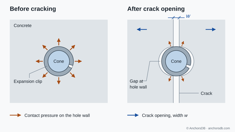
Figure 2. Reduction of expansion contact as a crack opens, before follow-up expansion. Crack width exaggerated.
Assessment of anchors for cracked concrete
Anchors for use in cracked concrete are assessed in tests with opened cracks through the anchor location and under repeated opening and closing of cracks. The ETA states whether cracked concrete is covered for each anchor size and embedment, and gives the corresponding resistances and displacements. An anchor assessed only for uncracked concrete may be used only where uncracked concrete has been verified.
Assessment for cracked concrete does not cover seismic loading, for which anchors are assessed separately in seismic performance categories C1 and C2, with wider cracks and, for C2, crack cycling.
The next guide explains anchor dimensions and notation.