
The loads on a fastening are resolved into forces on each anchor relative to the anchor axis. A force along the axis, acting away from the concrete, is tension. A force perpendicular to the axis is shear. An anchor subjected to both carries combined tension and shear.
The classification depends on the direction of the force relative to the anchor axis, not on the direction of gravity. The same downward force puts a ceiling anchor in tension and a wall anchor in shear.
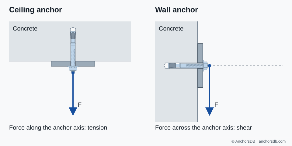
Figure 1. The same downward force on a ceiling anchor and a wall anchor.
Tension and shear forces
Tension is denoted by N and shear by V. Tension pulls the anchor out of the concrete; shear acts at the concrete surface and loads the anchor sideways. Where the fixture bears on the concrete or on a levelling mortar, a compressive force is carried by direct contact between fixture and concrete.
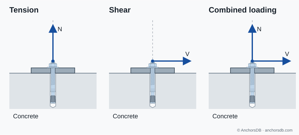
Figure 2. Tension, shear and combined loading at an anchor.
Forces and moments on the fixture
Loads act on the fixture, not directly on the anchors. EN 1992-4 requires the actions on the fixture to be converted into statically equivalent tension and shear forces on the individual anchors.
An inclined force is resolved into a component along the anchor axis and a component perpendicular to it. A moment on the fixture produces tension in the anchors on one side and compression between the fixture and the concrete on the other. Many fastenings therefore carry combined tension and shear, even where the applied load acts in a single direction.
Shear force and moment at a wall bracket
A stiff steel bracket is fixed to a concrete wall with an upper and a lower anchor row. A downward force F acts on the projecting arm at a distance e from the wall face.
The eccentricity produces a moment on the connection. The top of the bracket tends to rotate away from the wall and the bottom of the baseplate presses against it. Tension in the upper anchors and compression under the lower part of the plate resist the moment. The anchors also carry the downward force as shear.
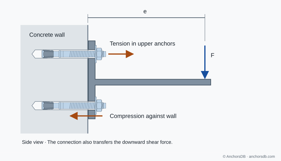
Figure 3. Forces from a stiff bracket on the anchors and the concrete.
The moment about the wall face is:
| Symbol | Quantity | Unit |
|---|---|---|
| Moment about the wall face | kN·m | |
| Downward force on the bracket | kN | |
| Perpendicular distance from the wall face to the line of action of | m |
For kN acting at m:
The connection carries 1 kN of shear and a moment of 0.30 kN·m. The same force applied further from the wall produces a proportionally larger moment and larger tension in the upper anchors.
The tension in each upper anchor depends on the anchor arrangement, the position of the compression resultant under the plate and the stiffness of the plate. The distribution of shear depends on the clearance between the anchors and the holes in the fixture: an anchor in contact with its hole wall is loaded before one with a gap. How an anchor group shares load explains these effects.
Shear with lever arm
The bracket above bears directly against the concrete. Where the fixture stands off the concrete surface, for example on levelling nuts, the shear force acts at a distance from the concrete. The anchor then acts as a short cantilever and is subjected to bending as well as shear.
EN 1992-4 assumes shear without lever arm only when the steel fixture is in contact with the anchor over at least half the fixture thickness and is fixed either directly to the concrete or on a levelling mortar no thicker than half the anchor diameter, placed under the full area of the fixture on a rough concrete surface, with a strength at least equal to that of the concrete and not less than 30 N/mm². Otherwise, the shear is normally taken to act with lever arm.
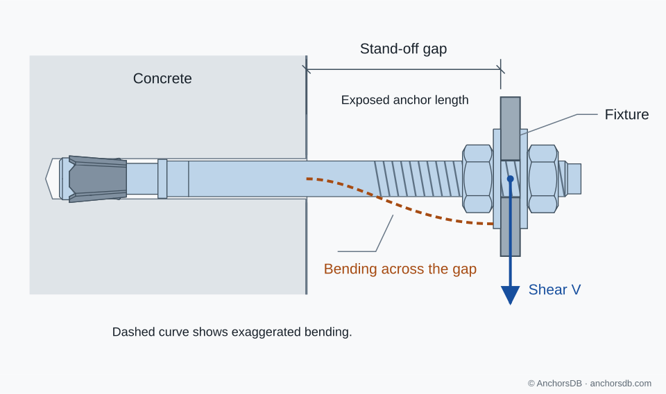
Figure 4. Shear across a stand-off gap bends the anchor. Deformation exaggerated.
Bending considerably reduces the shear the anchor steel can carry. EN 1992-4 therefore treats steel failure under shear with lever arm separately from shear without lever arm. The design bending moment depends on the lever arm and on whether the fixture restrains the anchor against rotation.
The two eccentricities have different effects. The projection of the bracket arm produces a moment on the whole connection. A stand-off gap produces bending in each individual anchor.
Tension–shear interaction
An anchor that satisfies its tension and shear checks separately can still fail under their combination. EN 1992-4 verifies the interaction using the ratios of design force to design resistance, and . Steel failure and the other failure modes are verified separately.
For steel failure:
For the other failure modes, using the largest ratios from the tension and shear checks:
with and in each case. The steel interaction is not checked separately for shear with lever arm, because the bending verification already includes it.
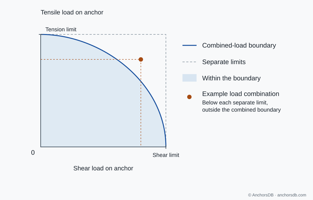
Figure 5. Separate limits and a combined-load boundary.
The next guide explains how anchors transfer these forces into concrete.