

An anchor drawing describes the steel element, the hole drilled into the concrete and the fixture being attached. Each has its own dimensions. Reading them together establishes how far the anchor enters the concrete, how it fits through the fixture and how much length remains for fastening.
Concrete surface and embedment reference
Embedment depths are measured from the surface of the load-bearing concrete, and drilling depths normally from the same surface. Plaster, screed, insulation or any other non-structural layer lies outside the embedment, although the anchor must pass through it.
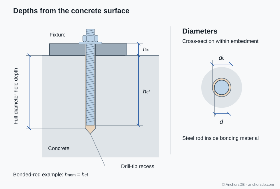
Figure 1. Dimensions for a bonded threaded rod.
Anchor diameter and hole diameter
For a threaded rod, M12 identifies a metric thread with a nominal diameter of 12 mm. The surrounding drilled hole has its own specified diameter, allowing space for the bonding material.
For mechanical anchors, the anchor designation, the bolt diameter and the outside diameter can differ. The sleeve of a heavy-duty sleeve anchor is wider than its bolt, and the thread of a concrete screw is wider than the hole into which it cuts. The installation data for each anchor size state the required drill-bit diameter.
| Symbol | Dimension | Where it applies |
|---|---|---|
| Bolt, rod or thread diameter | The steel element; read the drawing's definition | |
| Outside diameter of the fastener | May differ from the bolt or thread diameter | |
| Nominal drill-bit diameter | The hole drilled into the concrete | |
| Clearance-hole diameter | The hole through the fixture |
The clearance hole in the fixture is specified separately from the drilled hole in the concrete. Its size limits the gap between anchor and fixture, which affects how shear is shared between anchors in a group.
Effective and nominal embedment
Nominal embedment, commonly written , describes how far the anchor extends below the concrete surface.
Effective embedment, , is the depth used in calculations of concrete resistance. It is measured to the point at which the anchor transfers tension into the concrete, so it may be less than the depth to the anchor's tip. EN 1992-4:2018 defines it for each anchor type in Figures 3.1–3.3.
- Bonded rod: the bonded length within the concrete. For a plain threaded rod, normally equals (Figure 1).
- Headed anchor: the depth to the bearing face of the head. The head thickness lies below this point, so exceeds .
- Expansion, undercut and screw anchors: the depth stated in the European Technical Assessment (ETA) for each setting configuration.
The effective embedment for design is therefore taken from the ETA.
Drilled-hole depth
The hole must accommodate the installed anchor and any additional depth that its setting process requires. It can extend beyond the embedded steel, as in Figure 1. Additional hole depth does not increase the effective embedment.
Hole depth can be measured to the end of the full-diameter cylindrical hole or to the deepest point of the drill-tip recess. In Figure 1, it is measured to the end of the full-diameter hole. Product documentation does not follow a single convention, so the endpoints and the reference surface must be read from the installation data before the drill stop is set. Where the hole is drilled through the fixture, the reference may be the top of the fixture.
Fixture thickness and anchor length
The fixture is the attached bracket, plate or other component. Its thickness, usually written , is the plate thickness at the anchor when the plate bears directly on the concrete. Intervening layers, such as grout, packing or a non-structural finish, increase the length required above the concrete. Except for a thin levelling mortar that meets the conditions of EN 1992-4, such layers also cause shear to act on the anchor with lever arm; see tension, shear and combined loading.
A projecting threaded rod also needs length for the washer and nut, plus the required length of thread extending beyond the nut. A mechanical anchor of a given length may have a stated maximum fixture thickness for each permitted embedment. A thicker plate can require a longer anchor to preserve the selected embedment.
For an internally threaded anchor, the fixing bolt must be long enough for the specified length of bolt to screw into the anchor. Its length is selected together with the fixture thickness and any other layers in the connection.
Concrete thickness, spacing and edge distance
The concrete member and neighbouring anchors add three more dimensions:
| Symbol | Dimension | Measurement |
|---|---|---|
| Concrete member thickness | Between the member's opposite faces | |
| Anchor spacing | Centre to centre between anchors | |
| Edge distance | From the anchor centreline to a concrete edge |
A subscript min identifies a minimum permitted value, such as , or . These limits belong to the assessed anchor configuration. A hole fitting within the concrete thickness does not by itself establish that the minimum member thickness is satisfied.
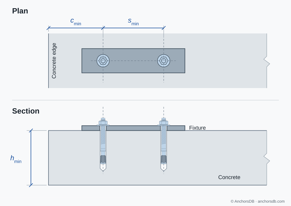
Figure 2. Measurement references for minimum edge distance, spacing and concrete thickness. Permitted values and combinations depend on the assessed anchor configuration.
Spacing and edge distance also influence resistance. See why concrete geometry affects anchor resistance for the effect of edges, embedment and overlapping breakout regions.
Dimensional checks for the selected anchor configuration
- Select the anchor size and effective embedment to identify the installation configuration.
- Check the drilling diameter, drilling depth and setting requirements for that configuration. Confirm that the fixture thickness, intervening layers and fastening components fit within the available anchor or bolt length.
- Compare the actual concrete thickness, edge distances and anchor spacing with the minimum values in the ETA.
Keep the dimensions for one installation configuration together: a product offered at several embedments may have different drilling depths, fixture-thickness limits and resistance data for each.
For the construction behind these dimensions, see types of concrete anchors. For force transfer along the embedment, see how anchors transfer loads into concrete.