

An anchor design check demonstrates that a fastening carries its design loads with adequate safety and acceptable displacement. In Europe it usually follows EN 1992-4, using product data from the European Technical Assessment (ETA) of the selected anchor. The check covers the anchor steel, the load transfer into the concrete, the concrete around the anchors and the member that carries the load onwards. A wall-mounted equipment bracket illustrates the sequence: its weight, any outward pull and the resulting moment pass through the plate and anchors into the wall.
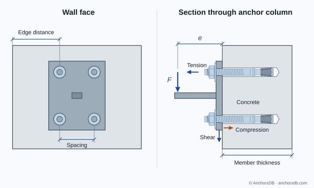
Figure 1. Loads and geometry for a wall-mounted connection.
Actions and connection geometry
The actions on the fixture are combined according to EN 1990, including forces from restrained deformation of the attached member, such as shrinkage or temperature change; these indirect actions carry their own partial factor, recommended as 1.2 for concrete failure modes. The geometry comprises the fixture dimensions and thickness, the anchor positions, spacing and edge distances, and the thickness of the concrete member. The concrete is described by its strength class and its condition: cracked, or uncracked where this is verified for the life of the fastening. Exposure, fire, seismic or fatigue loading add requirements to the selection and to the checks.
Anchor selection and scope of the ETA
The selected anchor must have an ETA covering the base material, concrete condition, loading type, drilling method and, for bonded anchors, the temperature range and hole condition. The member thickness, spacing and edge distances must meet the minimum values in the ETA, which prevent splitting during installation. The steel grade and corrosion protection are chosen for the exposure.
Forces on individual anchors
The actions on the fixture are converted into statically equivalent tension and shear forces on each anchor. Elastic analysis with a rigid fixture is the usual method: anchors carry tension, and compression passes through contact between fixture and concrete. Eccentricity and prying from fixture deformation are included; friction under the fixture is neglected. Shear distribution depends on the hole clearance: EN 1992-4 covers clearances up to the values in its Table 6.1, and for shear perpendicular to an edge closer than , only the anchors closest to the edge are assumed to resist it in the concrete edge check; all anchors are effective for steel and pry-out failure.
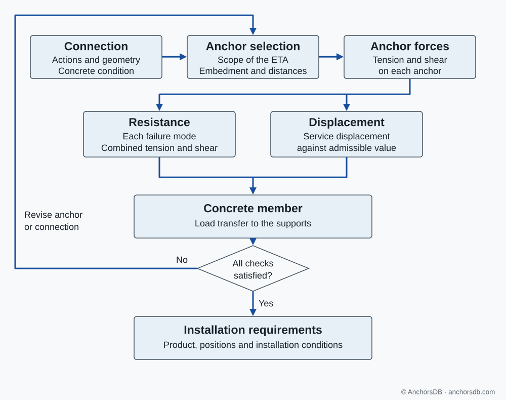
Figure 2. Main stages of an anchor design check.
Resistance for each failure mode
At the ultimate limit state, each failure mode is verified separately:
is the design force on the anchor or group, the characteristic resistance for that failure mode, and the partial factor for it. For concrete-related failure, is the concrete factor, recommended as 1.5, multiplied by the installation safety factor from the ETA. Steel failure is checked for the most highly loaded anchor; concrete failure modes involve the concrete volume shared by neighbouring anchors and are checked for the group.
| Load | Failure mode | Verified for |
|---|---|---|
| Tension | Steel failure | Most highly loaded anchor |
| Tension | Pull-out | Most highly loaded anchor |
| Tension | Concrete cone, combined pull-out and concrete failure of bonded anchors, splitting, blow-out | Group |
| Shear | Steel failure, with or without lever arm | Most highly loaded anchor |
| Shear | Pry-out and concrete edge failure | Group |
Where tension and shear act together, interaction checks combine the utilisations for steel and for concrete failure. The tension and shear failure modes, combined loading and partial factors are explained separately.
Displacement and the concrete member
At the serviceability limit state, the anchor displacements under service loads, taken from the short- and long-term values in the ETA, are compared with the displacement the supported element can accept. The displacement of the connection also includes fixture deformation and slip through hole clearance; see anchor displacement and stiffness.
The concrete member must carry the anchor loads to its supports. For anchors on the tension face of a member, Annex A of EN 1992-4 requires no additional shear verification of the member where, for example, its shear force including the anchor loads is no more than 80 % of its shear resistance, the anchor loads are small and widely spaced, hanger reinforcement carries them, or the embedment reaches at least 80 % of the member thickness.
Installation requirements in the design
The design result is valid only for the anchor and installation it assumes. The project specification therefore records:
- the anchor product, size, embedment and number, with the instruction that they must not be changed without the designer's approval;
- the anchor positions, spacing and edge distances, with positive tolerances only;
- the fixture thickness, clearance-hole diameter and any grout or other layer between fixture and concrete;
- the concrete strength class and the cracked or uncracked assumption;
- installation conditions from the ETA, such as the drilling method, hole cleaning, curing time or installation torque.
How an anchor group shares load explains force distribution in more detail.