
A tension load passes from the fixture into the anchor steel, from the steel into the concrete through the anchoring mechanism, and from there into the surrounding concrete. Each link in this path can fail. EN 1992-4 verifies each failure mode separately, using resistances from the European Technical Assessment (ETA) of the anchor or calculated from its parameters.
| Failure mode | Applies to | Source of the resistance |
|---|---|---|
| Steel failure | All anchors | ETA, for each steel grade |
| Pull-out | Mechanical anchors | ETA, from tests |
| Combined pull-out and concrete failure | Bonded anchors | Calculated from the bond strength in the ETA |
| Concrete cone | All anchors | Calculated from embedment, concrete strength and condition |
| Splitting | All anchors | Calculated, with characteristic distances from the ETA |
| Blow-out | Headed and undercut anchors close to a side face | Calculated |
Governing failure mode
The design resistance for each mode is compared with the design tension, and the lowest design resistance governs. Increasing the resistance of a mode that does not govern leaves the connection unchanged: a higher steel grade has no effect when concrete cone failure governs. Changes to the anchorage often shift the governing mode. A deeper embedment raises the concrete cone resistance until pull-out or steel failure becomes the governing mode.
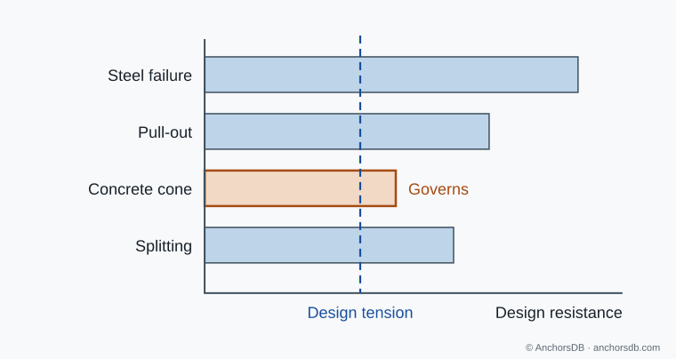
Figure 1. Governing failure mode in a tension check. Illustrative values.
Steel failure
The anchor steel fractures when the tension exceeds the resistance of its weakest cross-section. For a threaded element this is the stress area of the thread, which is smaller than the area of the plain shank of the same nominal diameter; in a throughbolt it can also be the reduced neck above the cone. The characteristic resistance is the stress area multiplied by the tensile strength of the steel, and the ETA states it for each size and steel grade. Steel failure is ductile in most anchor steels and is checked for the most highly loaded anchor.
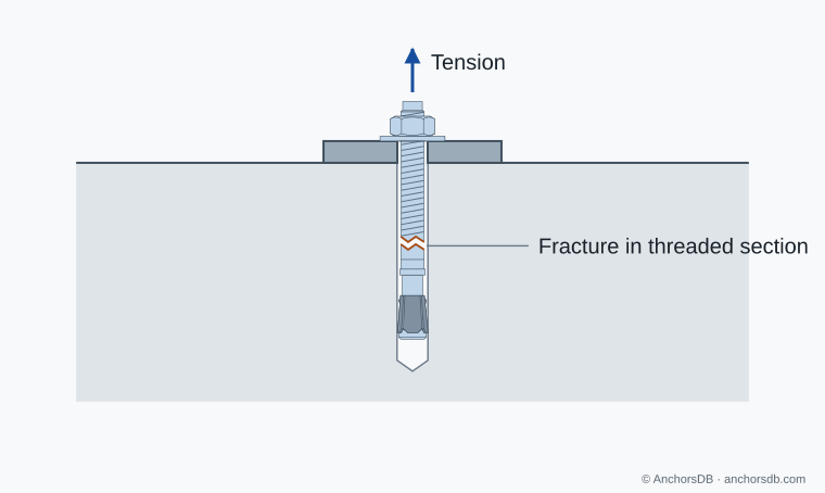
Figure 2. Steel failure under tension.
Pull-out and combined pull-out and concrete failure
In pull-out, the anchor leaves the hole while the concrete around it stays largely intact. In a torque-controlled expansion anchor, the cone pulls through the expansion clip, which stays in the hole (pull-through), or the anchor slides along the hole wall. In an undercut or headed anchor, the concrete above the bearing area crushes. The pull-out resistance is established by tests and given in the ETA for cracked and uncracked concrete. It is lower in cracked concrete, where the hole widens and the expansion force falls.
In a bonded anchor, the bond between mortar and concrete, or between rod and mortar, fails along the embedment, usually with a shallow concrete cone near the surface. EN 1992-4 calls this combined pull-out and concrete failure and calculates its resistance from the characteristic bond strength in the ETA. The bond strength depends on the concrete condition, the temperature range, the hole condition and the cleaning, and is reduced under sustained load.
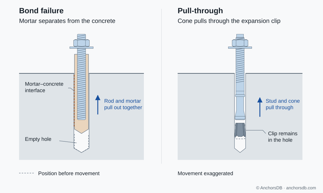
Figure 3. Bond failure of a bonded anchor and pull-through of a throughbolt.
Concrete cone failure
A crack starts at the load-transfer zone and runs to the surface at a shallow angle, detaching a cone-shaped body of concrete with the anchor still inside it. The diameter of the cone at the surface is about three times the effective embedment . The resistance increases with and with the square root of the concrete strength, and is lower in cracked concrete. An edge closer than about , or neighbouring anchors closer than about , cut into the cone and reduce the resistance; see why concrete geometry affects anchor resistance. Concrete cone failure is brittle and is checked for the group.
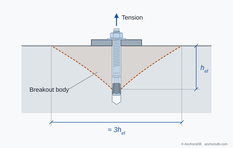
Figure 4. Concrete cone failure under tension.
Splitting
Expansion and bearing forces act radially on the concrete and can split the member along a line through the anchors. Splitting is most likely in narrow or thin members and at small edge distances and spacings. Splitting during installation is prevented by the minimum member thickness, edge distance and spacing in the ETA. Splitting under load is verified using the characteristic edge distance for splitting given in the ETA. No verification is needed where every edge distance is at least that value (1.2 times it for groups) and the member thickness is at least the value that corresponds to it in the ETA, or where the resistances are calculated for cracked concrete and reinforcement resists the splitting forces and limits the crack width to 0.3 mm.
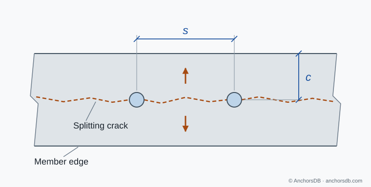
Figure 5. Splitting crack through an anchor row, in plan.
Blow-out
A headed anchor, or an undercut anchor acting as one, transfers its load through bearing at the head. Close to a side face, the lateral component of this bearing pressure pushes a wedge of concrete out of the side face at the level of the head. EN 1992-4 requires a blow-out check where the side edge distance is no more than half the effective embedment. The resistance depends on the side edge distance, the bearing area of the head and the concrete strength. It does not increase with embedment, so a deeper anchor at the same edge distance gains no blow-out resistance.
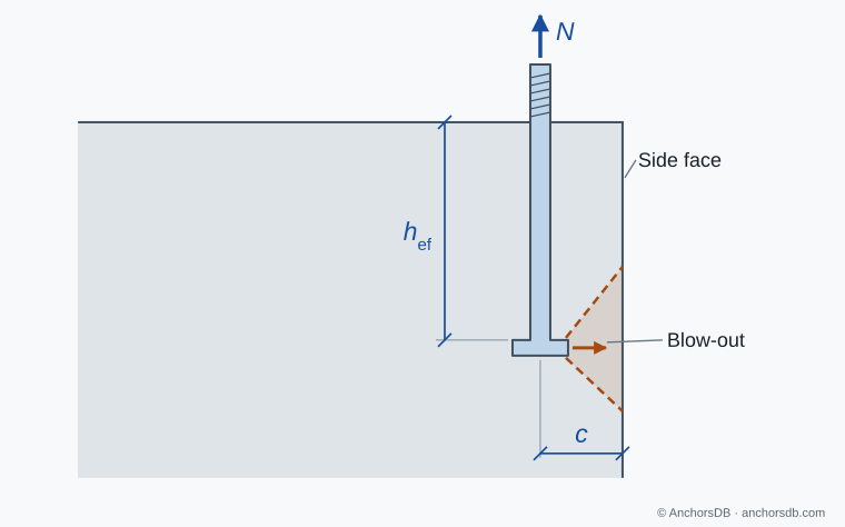
Figure 6. Blow-out at a side face.
For transverse loads, see anchor failure modes under shear; for the overall verification, see how an anchor design check works.