

An anchor is verified by comparing the force acting on it with its resistance for each failure mode. Both are forces, normally in kilonewtons. The terms characteristic, design and recommended state how a value was established and therefore which value it may be compared with: design actions with design resistances, and recommended loads, under the conditions the manufacturer defines, with unfactored (characteristic) loads.
Actions and resistance
Self-weight, imposed loads, wind and other loads on the fixture are actions. Structural analysis converts them into tension and shear forces in each anchor, the action effects.
The resistance is the force an anchor or anchor group can carry for one failure mode: steel failure, pull-out, combined pull-out and concrete failure of bonded anchors, concrete cone, splitting or blow-out under tension, and steel failure, concrete edge failure or pry-out under shear. Each depends on the anchor, the concrete, the geometry and the installation. Because the modes are verified for different loads, such as the most highly loaded anchor or the whole group, the mode with the highest ratio of action to resistance governs.
Resistance tables and ETAs use a consistent notation. denotes tension and shear; subscript E denotes an action effect and R a resistance; k denotes a characteristic value and d a design value. is therefore the design tension force on an anchor, and the characteristic resistance to concrete cone failure.
Mean and characteristic resistance
Nominally identical anchors tested to failure under the same conditions give scattered failure loads. The mean ultimate resistance is the average of the series.
The characteristic resistance is the 5 % fractile of the resistance: the value that 95 % of anchors are expected to exceed, determined with a confidence level of 90 %.
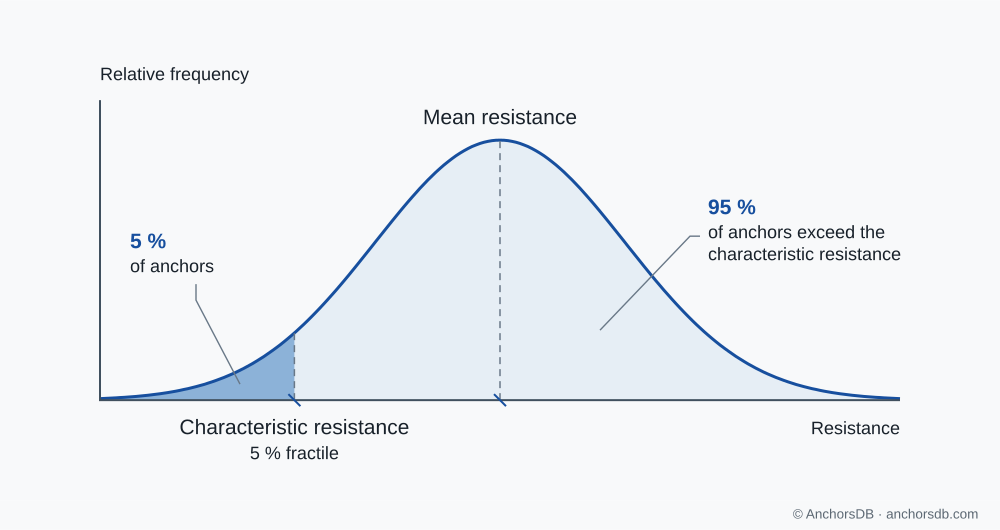
Figure 1. Mean and characteristic resistance.
A European Technical Assessment (ETA) gives characteristic resistances for defined conditions, such as anchor size, embedment, cracked or uncracked concrete, temperature range and installation method. For concrete-related failure modes, the characteristic resistance of the actual fastening is then calculated from these data for its edge distances, spacing and member thickness.
Partial factors and design values
The partial-factor method applies separate safety margins to actions and to resistance.
- Design action effect: the characteristic action effect multiplied by a partial factor for actions. EN 1990 recommends 1.35 for permanent and 1.5 for variable actions in persistent and transient design situations. Where several actions occur together, the applicable load combinations determine the design action effect.
- Design resistance: the characteristic resistance divided by a partial factor for the failure mode. EN 1992-4 recommends at least 1.4 for steel failure in tension. For concrete-related failure modes, the factor is 1.5 multiplied by an installation safety factor that reflects the sensitivity of the product to installation. For post-installed anchors in tension, the installation safety factor is given in the ETA, typically 1.0, 1.2 or 1.4; in shear it is 1.0.
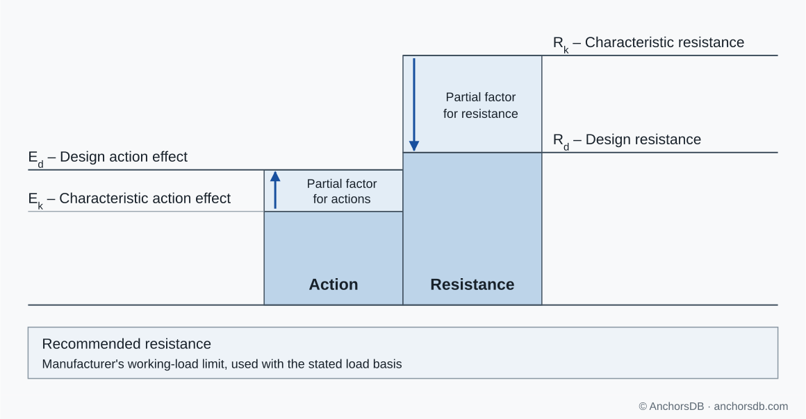
Figure 2. Characteristic and design values of action and resistance.
Temperature, load duration and other service conditions can already be included in the assessed resistance data. The data for the relevant conditions are used, and only the further reductions required by the ETA or the design method are applied; a reduction already included in a value is not applied again.
Design check
The fastening is adequate when, for every failure mode, the design action effect does not exceed the design resistance. Both values must refer to the same force direction and to the same anchor or anchor group.
In an illustrative tension check, an anchor carries a characteristic tension of 8 kN from combined permanent and variable loads. A single action factor of 1.4, between the factors for permanent and variable actions, is assumed for simplicity; a real design uses the applicable load combination. The design tension is 1.4 × 8 kN = 11.2 kN. The characteristic concrete cone resistance is 30 kN, and the ETA gives an installation safety factor of 1.4, so the partial factor is 1.5 × 1.4 = 2.1. The design resistance is 30 kN / 2.1 = 14.3 kN.
Since 11.2 kN does not exceed 14.3 kN, the check is satisfied for concrete cone failure. The other failure modes are checked in the same way, and combined tension and shear are checked for interaction, as explained in tension, shear and combined loading.
Recommended loads
A recommended load, or recommended resistance, is a manufacturer's working-load limit for specified conditions. It is compared with the unfactored applied load. On site, recommended loads are often called safe working loads (SWL).
Its derivation varies between manufacturers. A catalogue may apply assumed partial factors to an assessed resistance, or a global safety factor to a characteristic or mean ultimate resistance. The manufacturer's definition establishes which. Before using a recommended value, identify:
- The force direction it applies to: tension, shear or a stated combination.
- The anchor size, embedment and concrete condition it covers.
- The safety factors and load assumptions included.
- The edge distance, spacing and fixture assumptions of the table.
Values in resistance tables
The symbol identifies the type of value: is a characteristic tension resistance and a design tension resistance. A value headed "recommended load" requires the manufacturer's accompanying definition. The row conditions and footnotes then establish where the value applies; the distinction between cracked and uncracked concrete, for example, determines which resistance data are valid. See cracked vs uncracked concrete and anchor dimensions and notation for those inputs.
To compare the practical choices for a fixing, see mechanical vs chemical anchors.