
A shear load acts across the anchor axis. The fixture bears against the anchor, and the anchor bears against the concrete close to the surface. EN 1992-4 verifies four shear failure modes, using resistances from the European Technical Assessment (ETA) of the anchor or calculated from its parameters.
| Failure mode | Typical situation | Source of the resistance | Verified for |
|---|---|---|---|
| Steel failure without lever arm | Far from edges, fixture clamped to the concrete | ETA | Most highly loaded anchor |
| Steel failure with lever arm | Stand-off fixtures and thick intervening layers | Bending resistance in the ETA | Most highly loaded anchor |
| Pry-out | Short, stiff anchors | Concrete cone or bond resistance multiplied by a factor from the ETA | Group |
| Concrete edge failure | Shear towards a nearby edge | Calculated from edge distance, anchor diameter and concrete strength | Anchors closest to the edge |
Load transfer in shear
At first, friction under a clamped fixture carries part of the shear; EN 1992-4 neglects it. Once the fixture slips through the hole clearance, it bears on the anchor, which bears on the concrete over a short length below the surface. The high local pressure spalls a shallow wedge of concrete in front of the anchor, moving the bearing point deeper and adding bending to the shear in the steel. Displacements at failure are therefore considerably larger in shear than in tension.
Steel failure
Where the steel fixture is fixed directly to the concrete, or on a levelling mortar no thicker than half the anchor diameter, and bears on the anchor over at least half its thickness, the shear acts without lever arm. The anchor then fails in combined shear and bending just below the surface. The ETA gives the characteristic resistance for each size and steel grade. A sleeve that passes through the fixture hole adds to the steel cross-section where the ETA includes it.
Where the fixture stands off the concrete, or a thicker layer of grout or insulation lies between them, the shear acts with lever arm and bends the exposed length of the anchor. The resistance then follows from the bending resistance in the ETA, the lever arm and the rotational restraint at the fixture, and is much lower; see tension, shear and combined loading.
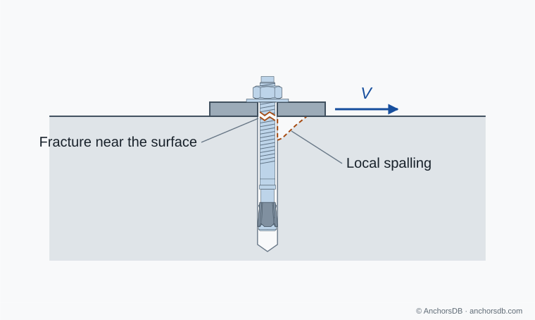
Figure 1. Steel failure under shear.
Concrete edge failure
Shear directed towards a nearby free edge splits off a half-cone of concrete between the anchor and the edge. In the idealised body used by EN 1992-4, the fracture reaches the edge over a width of about and extends to a depth of about on the edge face, where is the edge distance in the direction of the shear. The resistance increases with about , and less strongly with the anchor diameter and embedment and with the square root of the concrete strength. Close to an edge, this mode often limits the shear resistance well below the steel resistance.
The resistance is reduced where the member is thinner than , where a second edge lies within , or where neighbouring anchors are closer than . Shear parallel to the edge gives twice the resistance of shear towards it. In cracked concrete, straight edge reinforcement with stirrups or mesh at no more than 100 mm and no more than increases the resistance by 40 %, provided the embedment is at least 2.5 times the cover to that reinforcement. Only the anchors closest to the edge are taken as resisting shear in this check.
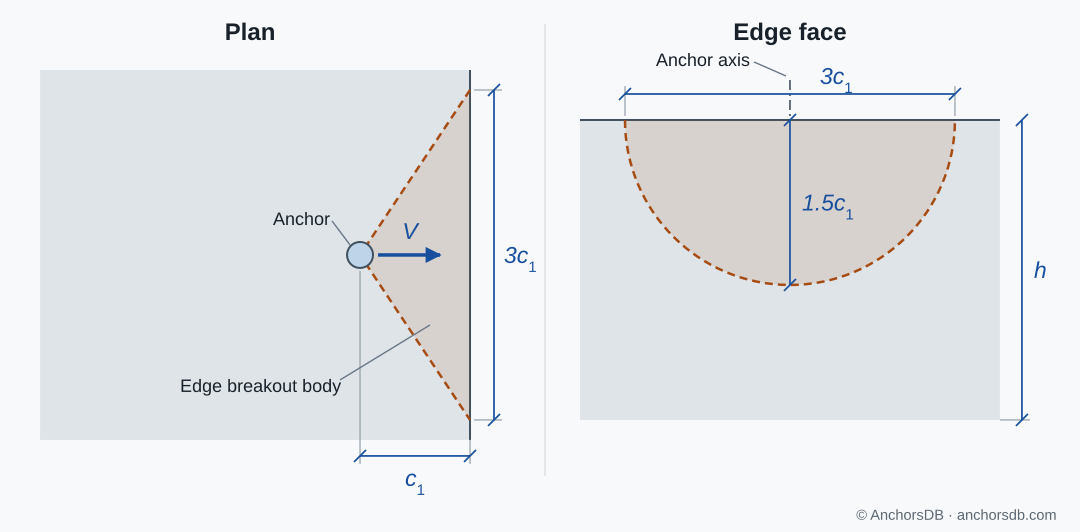
Figure 2. Concrete edge failure under shear.
Pry-out
A short, stiff anchor loaded in shear rotates in the concrete. Its embedded end pushes back against the concrete on the side opposite to the load and levers out a body of concrete behind the anchor. The pry-out resistance is the concrete cone resistance of the anchor or group, or for bonded anchors the lower of the cone and bond resistances, multiplied by a factor from the ETA. This factor is typically 1 for small embedments and 2 for larger ones, so pry-out mainly limits shallow anchors far from edges.
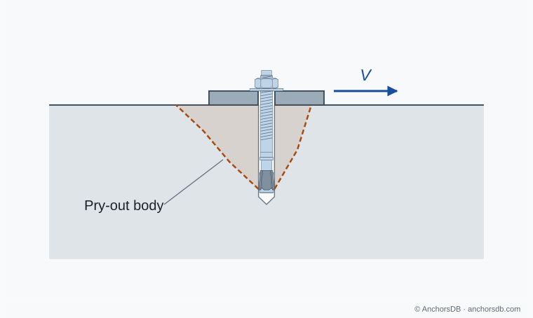
Figure 3. Pry-out of a shallow anchor under shear.
For fixture-hole clearance and shear distribution in groups, see how an anchor group shares load; for tension, see anchor failure modes under tension.