

Displacement is the movement of the loaded end of an anchor relative to the concrete, measured in the direction of the load. A fastening can displace enough to misalign equipment, open façade joints or overload a supported element while remaining well below its failure load. EN 1992-4 therefore verifies displacement separately from resistance: at the serviceability limit state, the displacement under the relevant actions must not exceed the admissible displacement for the application. Stiffness relates load to displacement; a stiffer connection displaces less under the same load.
Components of connection displacement
The displacement of an anchor combines slip relative to the concrete, elastic elongation of the steel and local deformation of the concrete in the load-transfer zone. Slip depends on the load-transfer mechanism. Undercut anchors and headed fasteners bear on the concrete, so their displacement depends on the bearing area and the initial fit. Torque-controlled expansion anchors displace further as the cone is drawn into the expansion sleeve under load. Displacements in cracked concrete are larger than in uncracked concrete.
The displacement of the complete connection adds the deformation of the fixture, compression of any grout or levelling layer and, under shear, slip of the fixture through the hole clearance. Shear displacements are therefore generally larger than tension displacements. EN 1992-4 applies to a group only where all its anchors are of the same type and size, because a common load–displacement behaviour is needed for the anchors to share load as assumed in the design.
Displacements in the European Technical Assessment
The European Technical Assessment (ETA) of an anchor gives characteristic displacements for a stated tension load and a stated shear load, in cracked and uncracked concrete. The short-term values and apply on loading. The long-term values and include the effects of sustained load and, in cracked concrete, of crack opening and closing; see sustained loading, creep and fatigue.
EN 1992-4 allows displacement to be taken as proportional to load, so the ETA values can be scaled to the load in each anchor. Under combined tension and shear, the two components are added vectorially. For example, with illustrative ETA values of mm at 6 kN and mm at 10 kN, an anchor carrying 3.6 kN tension and 6 kN shear displaces 0.3 mm and 1.2 mm in the two directions:
This is the displacement of the anchor. Fixture deformation and slip through the hole clearance are added to obtain the displacement of the connection.
Admissible displacement
EN 1992-4 leaves the admissible displacement to the designer, who sets it for the application: for example, the alignment tolerance of machinery or rails, the joint movement a façade element can accommodate, or the deflection limit of the supported member. Where anchors connect a stiff, statically indeterminate element, their displacement changes the distribution of forces and should be included in the structural analysis.
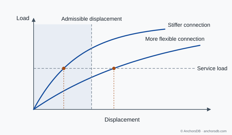
Figure 1. Displacement of two connections at the same service load. Schematic curves.
Brittle and ductile behaviour
A brittle response loses resistance over a small additional displacement after its peak. A ductile response sustains load over a large deformation before failure. Concrete cone, splitting and edge failures are brittle. Steel failure is ductile when the steel has sufficient elongation capacity and the anchor has a sufficient free length over which it can stretch. A torque-controlled expansion anchor with an adequate expansion reserve can behave in a similar way when the cone is pulled through the sleeve. Reduced spacing or edge distance can change the governing failure mode to concrete failure, with a correspondingly brittle response.
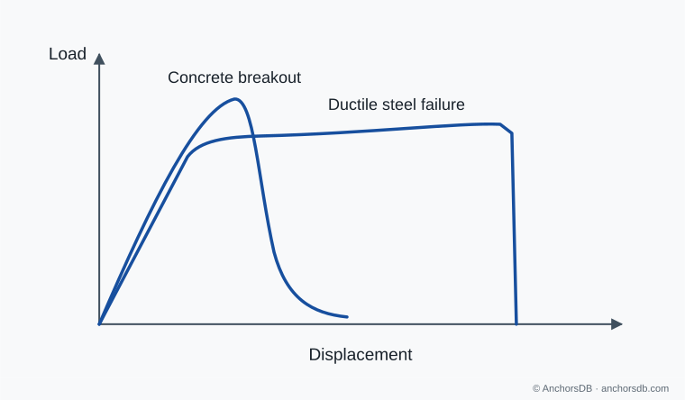
Figure 2. Brittle and ductile load–displacement responses. Schematic curves.
Deformation capacity gives visible warning of overload and, in a group, allows load to redistribute from the most highly loaded anchor to the others. EN 1992-4 accounts for it in several places:
- Plastic analysis of anchor groups at the ultimate limit state is permitted only under the conditions of CEN/TR 17081, which rely on ductile steel failure of the anchors.
- The steel shear resistance of anchors in a group is multiplied by a factor from the ETA, typically 1.0 for ductile steel and 0.8 for steel with a rupture elongation of 8 % or less.
- In seismic design relying on ductile fasteners, the load-transferring steel must have a nominal ultimate strength of at most 800 N/mm², a yield-to-ultimate strength ratio of at most 0.8 and a rupture elongation of at least 12 %, with a stretch length of at least 8 times the fastener diameter unless analysis justifies a shorter one.
Strength and elongation depend on the steel grade, which is also selected for the exposure; see corrosion and anchor materials.
For fixture stiffness and hole clearance in groups, see how an anchor group shares load; for the failure modes that limit resistance, see anchor failure modes under tension and under shear.