

A fixture secured by several anchors transfers its load to them as individual tension and shear forces. EN 1992-4 derives these forces by elastic analysis from the position of the load, the stiffness of the fixture and the clearance between each anchor and its fixture hole. The steel and pull-out checks are then made for the most highly loaded anchor, and the concrete checks for the group. Friction between the fixture and the concrete is neglected.
| Action on the fixture | Distribution to the anchors | Condition |
|---|---|---|
| Tension and bending | Linear strain distribution; anchors in the compression zone carry no tension | Rigid fixture |
| Shear | Shared equally by all anchors | Hole clearance within the EN 1992-4 limits; far from edges, or for the steel and pry-out checks |
| Shear towards a near edge | Carried by the anchors closest to the edge | Concrete edge failure check |
| Torsion | Perpendicular to the line from the group centroid, in proportion to the distance from it | All anchors effective |
Tension and bending on a rigid fixture
The fixture is assumed to remain plane, as a cross-section does in reinforced concrete design, and all anchors are assumed to have the same axial stiffness. Anchor tension then increases linearly with distance from the neutral axis. Where part of the fixture bears on the concrete, the fixture transfers that compression directly, and the anchors within the compression zone carry no tension.
A tensile load at the centre of a symmetrical group gives each anchor an equal share. Moving the load away from the centre adds a moment. In the two-anchor fixture of Figure 1, an offset of a quarter of the anchor spacing raises the load on one anchor to 0.75 of the total and reduces the other to 0.25. The total load is unchanged, but the most highly loaded anchor carries 50 % more.
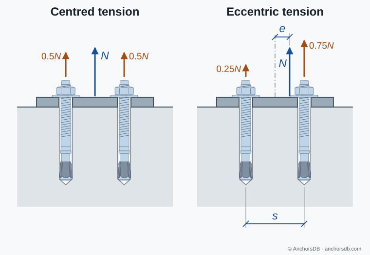
Figure 1. Centred and eccentric tension on a rigid two-anchor fixture.
Unequal anchor forces also reduce the concrete resistance of the group. The resultant tension then acts eccentrically to the centroid of the tensioned anchors, and EN 1992-4 reduces the resistances to concrete cone failure, combined pull-out and concrete failure, splitting and blow-out by an eccentricity factor.
Fixture stiffness and prying
EN 1992-4 treats a fixture as rigid when it remains elastic under the design actions and its deformation is negligible compared with the axial displacement of the anchors. A thinner or unstiffened plate bends between the attachment and the anchors. Its outer edges, or toes, then press on the concrete, and the plate levers about them. This prying force adds to the tension in the anchors.
Prying increases with the flexibility of the plate and the projection of the toes beyond the anchors, and is greatest under predominantly tensile load. Where the fixture cannot be treated as rigid, the calculation of anchor forces must include its elastic deformation. A thicker plate, stiffeners or shorter toe projections reduce prying.
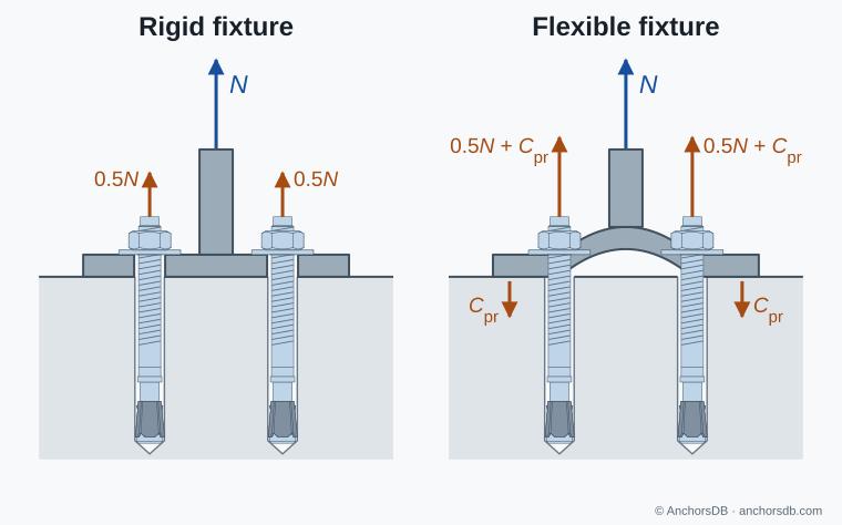
Figure 2. Anchor loads with a rigid and a flexible fixture. Deformation is exaggerated and the prying force is illustrative.
Shear distribution and hole clearance
Under shear, the fixture slips through the clearance around the anchors before its hole walls bear on them. Positioning tolerances leave each anchor at a different place in its hole, so one anchor is loaded first and the others engage only after further slip and deformation. EN 1992-4 covers fastenings without clearance and fastenings whose clearance holes do not exceed its Table 6.1 limits: 1 mm over the diameter of the bearing part for 6 and 8 mm, 2 mm for 10 to 24 mm and 3 mm from 27 mm. The bearing part is the bolt or, for a sleeve anchor whose sleeve passes through the fixture, the sleeve.
Within these limits, all anchors are taken as effective in resisting shear: in the steel failure and pry-out checks, for groups far from edges (), and under torsion or shear parallel to an edge. An anchor in a hole slotted in the direction of the shear carries no shear. A clearance filled with mortar of at least 40 N/mm² compressive strength, or eliminated by other suitable means, counts as no clearance; so do anchors welded or screwed to the fixture.
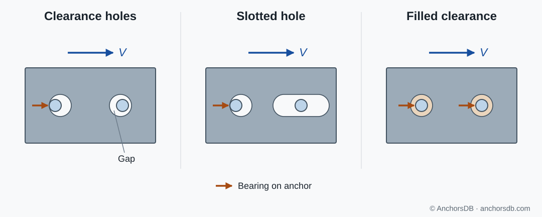
Figure 3. Plan sections at the fixture plate under shear. Clearances are exaggerated.
For the concrete edge failure check of a group close to an edge and loaded towards it, only the anchors closest to the edge are taken as resisting the shear, because the edge can break out before the anchors further back take up load. Components parallel to the edge are shared equally by all anchors, and a component directed away from the edge may be neglected. Where the anchors closest to the edge carry different loads, an eccentricity factor reduces the edge resistance, as in tension.
Torsion and combined shear
A shear force whose line of action passes beside the group centroid, or a moment about an axis normal to the concrete surface, twists the fixture in its plane. All anchors resist this torsion. Each anchor is loaded perpendicular to the line joining it to the centroid and in proportion to its distance from it, so the outermost anchors of a group carry the largest torsion loads.
A shear force through the centroid is shared equally, and each anchor carries the vector sum of its shear and torsion components. The components add at the anchors on one side of the group and partly cancel at those on the other. The most highly loaded anchor therefore depends on the direction of the shear and the sense of the torsion.
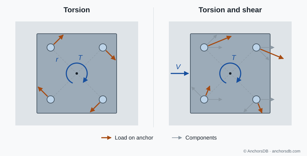
Figure 4. Anchor loads in a four-anchor group under torsion, alone and with shear.
The resistances checked against these anchor loads are described in anchor failure modes under tension and anchor failure modes under shear. Overlapping breakout bodies of closely spaced anchors are covered in why concrete geometry affects resistance.