

The resistances in the European Technical Assessment (ETA) of an anchor are determined in short-term tests. A load that acts for many years, or that is repeated many times, can cause failure below that short-term resistance: bonded anchors creep under sustained tension, and steel and concrete accumulate fatigue damage under repeated load. EN 1992-4 reduces the bond resistance of bonded anchors for sustained load and requires a separate fatigue verification for frequently repeated loads.
Sustained and repeated loads
A sustained load acts over a long period. In EN 1992-4 it comprises the permanent actions and the permanent component of the variable actions, such as the self-weight of a suspended ceiling or the operating weight of pipework. A repeated load varies between a minimum and a maximum . Fatigue depends on the load range and the number of cycles. A machine support usually carries both: its self-weight as a sustained load and the operating forces as a repeated load.
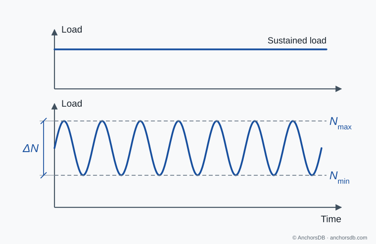
Figure 1. Sustained and repeated load histories.
Creep of bonded anchors
The polymer mortar of a bonded anchor continues to deform under constant stress. This time-dependent deformation is creep. After the initial displacement on loading, the displacement increases with time. At moderate stress and temperature the rate decreases and the displacement stabilises. At high stress or temperature the rate increases again until the bond fails. Creep increases with the proportion of the bond strength that is sustained and with the temperature of the concrete around the anchor, and it differs considerably between mortars.
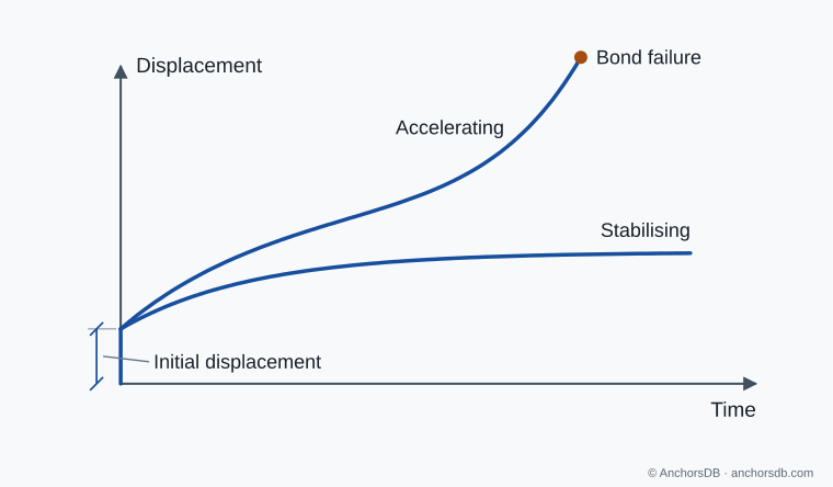
Figure 2. Displacement of a bonded anchor under sustained tension.
The displacement of mechanical anchors also increases under sustained load, to a smaller extent. The long-term displacements given in the ETA include this effect; see anchor displacement and connection stiffness.
Sustained load in the design of bonded anchors
Bonded anchors are assessed in sustained-load tests at elevated temperature, and the ETA gives a factor for the product. The designer determines the ratio of sustained to total design load. Where that ratio exceeds , EN 1992-4 reduces the bond resistance by the difference. For example, with and 80 % of the load sustained, the bond resistance is multiplied by 0.8. Where the ETA gives no value, is used; it relates to a sustained tension load over a design life of 50 years, including at least 10 years at a concrete temperature of 43 °C.
The ETA also states temperature ranges for which the bond resistances apply, each with a maximum long-term and a maximum short-term temperature, for example 24 °C and 40 °C, or 50 °C and 80 °C. The long-term temperature is the one relevant to creep. Overhead installations, heated plant rooms and surfaces exposed to the sun can exceed the lower ranges.
Ceiling collapse in the Boston Interstate 90 connector tunnel
On 10 July 2006, a section of the suspended concrete ceiling in Boston's Interstate 90 connector tunnel fell onto a car, killing a passenger. About 26 US tons (approximately 24 tonnes) of concrete and suspension hardware fell. The ceiling was suspended from the tunnel roof on epoxy bonded anchors.
The US National Transportation Safety Board found that the epoxy adhesive had poor creep resistance. Under the permanent weight of the ceiling, the adhesive deformed and fractured over several years until several anchors pulled out. An anchor displacement in another part of the tunnel system in 1999 was not identified as creep, and the ceiling was not inspected between the tunnel's opening in 2003 and the collapse.
The adhesive carried the weight of the ceiling on installation and failed under it over time. In Europe, bonded anchors are assessed in sustained-load tests at elevated temperature, and the design reduces their bond resistance for sustained load.
Fatigue under repeated loading
Under repeated stress, a crack can initiate at a stress concentration, such as a thread root, and grow by a small amount in each cycle, even when the maximum load is well below the static resistance. When the remaining section can no longer carry the load, it fractures in a single cycle. The fracture surface shows the two zones: a smooth fatigue zone with curved beach marks spreading from the origin, and a rough final fracture. Fatigue life is governed mainly by the load range, and threaded steel has a low fatigue resistance. Concrete also accumulates fatigue damage; EN 1992-4 takes the fatigue resistance of the concrete failure modes as half the static resistance for 2 million cycles.
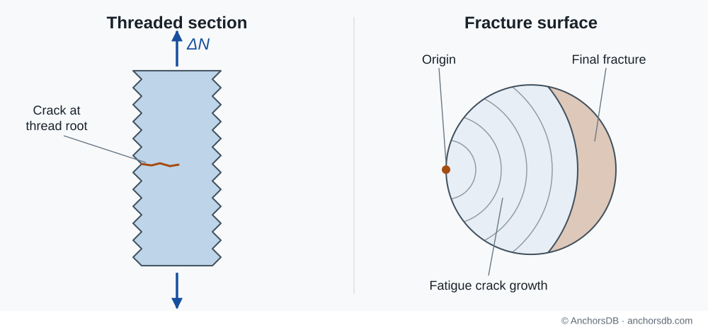
Figure 3. Fatigue crack in a threaded anchor.
EN 1992-4 requires a fatigue verification for frequently repeated loads, for example on crane runways, reciprocating machinery and lift guide rails. Only anchors whose ETA covers fatigue loading may be used, and the fastening is verified for both static and fatigue loading. The standard also requires:
- no annular gap between the anchor and the fixture hole
- a permanent preload in the anchor throughout its service life, with the nut secured against loosening
- shear without lever arm
While the fixture remains clamped, a large part of the load variation is carried by the clamped joint and the stress range in the anchor is reduced. Loss of preload increases the stress range; see installation torque and preload. For the bond mechanism, see resin bonded anchors.