

An anchor transfers its force into concrete by friction, mechanical interlock (bearing) or bond. Whatever the mechanism, the force must then spread through the surrounding concrete, normally without the help of reinforcement. Anchor resistance in concrete therefore depends on the tensile strength of the concrete, and this governs much of anchor behaviour: the formation of a concrete cone, the reduction in resistance in cracked concrete, and the influence of embedment, edges and spacing.
Load path from fixture to member
A tension force on a fastening passes through:
Fixture → anchor → anchorage zone → concrete member.
The anchorage zone is the concrete around the embedded part of the anchor, where force passes from the anchor into the member. Resistance can be limited by the anchor steel, by the transfer between anchor and concrete, by the concrete of the anchorage zone or by the member as a whole.
Friction: radial pressure on the hole wall
In an expansion anchor, the expanded sleeve or clip presses radially against the hole wall. The friction produced by this pressure is in equilibrium with the tension in the anchor. Under increasing load, the expansion element can also indent the concrete locally.
The radial pressure acts on the concrete at all times, including before any external load is applied. It produces circumferential tensile stresses around the hole, which can split the concrete if the anchor is too close to an edge, too close to another anchor or installed in too thin a member. Under load, the expansion element transfers the tension further into the concrete, as shown in Figure 1.
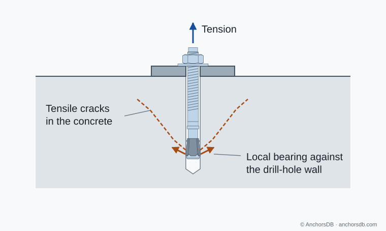
Figure 1. Local pressure at an expansion anchor and tensile cracking in the surrounding concrete.
Bearing: concentrated compression
In a cast-in headed anchor, an undercut anchor or a concrete screw, a head, segment or thread flank bears directly on the concrete. The bearing stress at the contact is high and compressive. The concrete can usually carry it locally; the limit lies in the surrounding concrete, where the force spreads out and produces tensile stresses.
Because bearing anchors do not depend on friction, they need no permanent expansion pressure to hold. Cast-in headed anchors therefore introduce no splitting forces during installation, and undercut anchors introduce considerably lower splitting forces than expansion anchors.
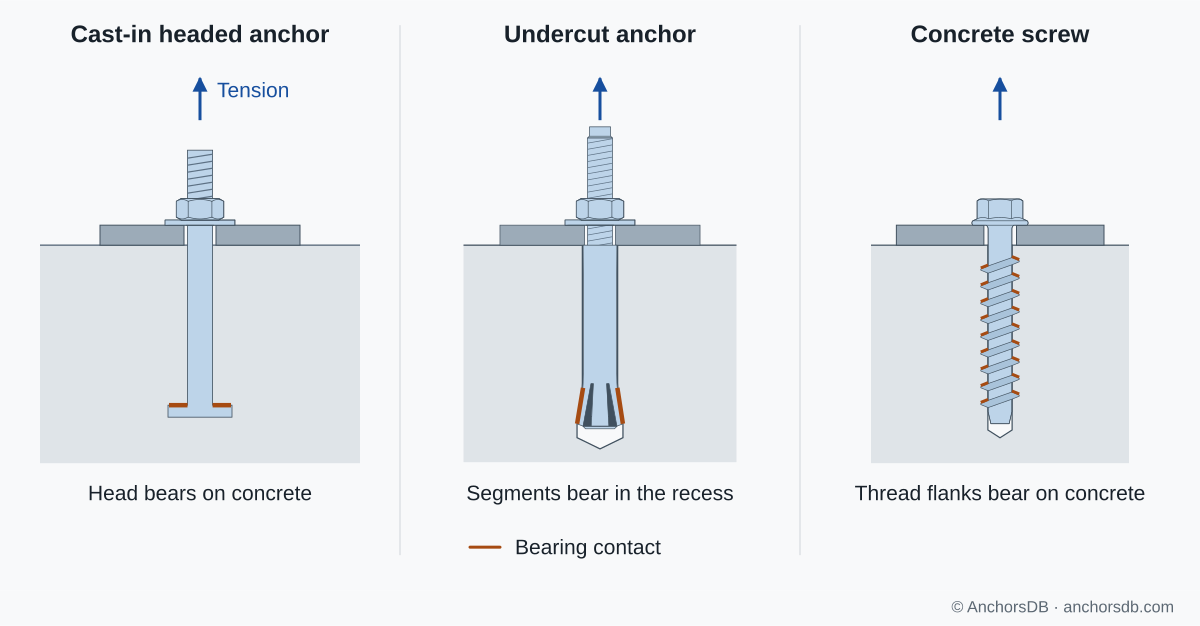
Figure 2. Bearing contacts in three types of mechanical interlock.
Bond: transfer along the embedded length
In a bonded anchor, force passes from the steel element to the hardened mortar and from the mortar to the hole wall. Bond at each interface is a combination of adhesion and micro-keying, the interlock of the mortar with the roughness of the steel and the hole wall. A threaded rod or ribbed bar also interlocks mechanically with the mortar.
Bond stress is not uniform along the embedment. At service loads it is highest near the concrete surface, at the loaded end of the bonded length. As load increases, a shallow concrete cone can form near the surface, and the remaining load is redistributed along the deeper part of the embedment. Bonded anchors can therefore fail by pull-out, by a concrete cone or by a combination of a shallow cone and pull-out of the deeper part.
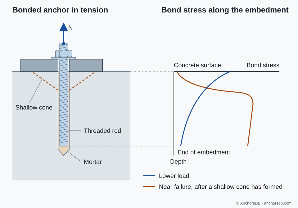
Figure 3. Bond stress along a bonded anchor at lower load and near failure. Schematic distributions.
The bond strength is specific to the product and depends on the concrete strength and condition, the drilling method, hole cleaning, the moisture condition of the hole, the service temperature and the duration of loading. It can only be determined by testing the particular system.
Concrete tensile strength and the concrete cone
Concrete has a tensile strength of only about a tenth of its compressive strength. Whichever mechanism transfers the load, the tension in an anchor must ultimately be carried by tensile stresses in the concrete around it. When those stresses exceed the tensile strength, cracks form and spread from the embedded end of the anchor towards the surface, separating a roughly conical body of concrete: the concrete cone.
This explains the main factors that control anchor resistance in concrete:
- Embedment depth: a deeper anchor engages a larger cone and so a larger area of concrete in tension.
- Edges and spacing: an edge or a neighbouring anchor truncates or overlaps the cone, reducing the concrete available to carry tension.
- Cracks: a crack through the anchorage zone interrupts the tensile stress field and reduces resistance.
Reinforcement in the member does not normally contribute to this local resistance unless it is specifically designed and detailed for the anchor load. The effects of cracking and geometry are explained in cracked vs uncracked concrete and how concrete strength and geometry affect anchor resistance.
Shear transfer
A shear force passes from the fixture to the anchor by bearing at the fixture hole and from the anchor into the concrete by bearing near the concrete surface. The high local bearing stress can spall a shallow piece of concrete in front of the anchor. The bearing point then moves deeper, increasing the lever arm and the bending in the anchor. Shear displacements at failure are therefore considerably larger than tension displacements.
Where the fixture is clamped against the concrete, friction under the fixture initially carries part of the shear. Once friction is overcome, the fixture slips through the clearance in its hole until it bears on the anchor. EN 1992-4 neglects this friction in design.
Where the fixture stands off the concrete surface, the shear force acts with a lever arm and bends the anchor. Tension, shear and combined loading describes these force combinations.
Load transfer through the concrete member
After the force leaves the anchorage zone, the slab, beam or wall carries it to its supports. A fastening with adequate local resistance can still overload the member. EN 1992-4 Annex A requires the transmission of fastener loads to the supports to be demonstrated in accordance with EN 1992-1-1. For loads applied to the tension face of a member, it lists conditions under which no additional check of the member's shear resistance is needed: limited shear utilisation of the member, a small fastener tension force with sufficient spacing between fastenings, hanger reinforcement for the fastener loads, or an embedment of at least 0.8 times the member thickness.
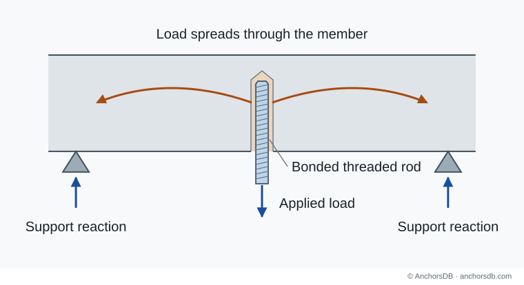
Figure 4. Local anchorage within the load path of a supported concrete member.
The next guide explains the difference between cracked and uncracked concrete and its effect on anchors.