

The installation arrangement describes the position of the anchor relative to the fixture. Three arrangements are distinguished: pre-positioned, through-fixing and stand-off. The arrangement determines the drilling sequence, the clearance-hole diameter in the fixture, the required anchor length and the path by which shear passes from the fixture into the anchor.
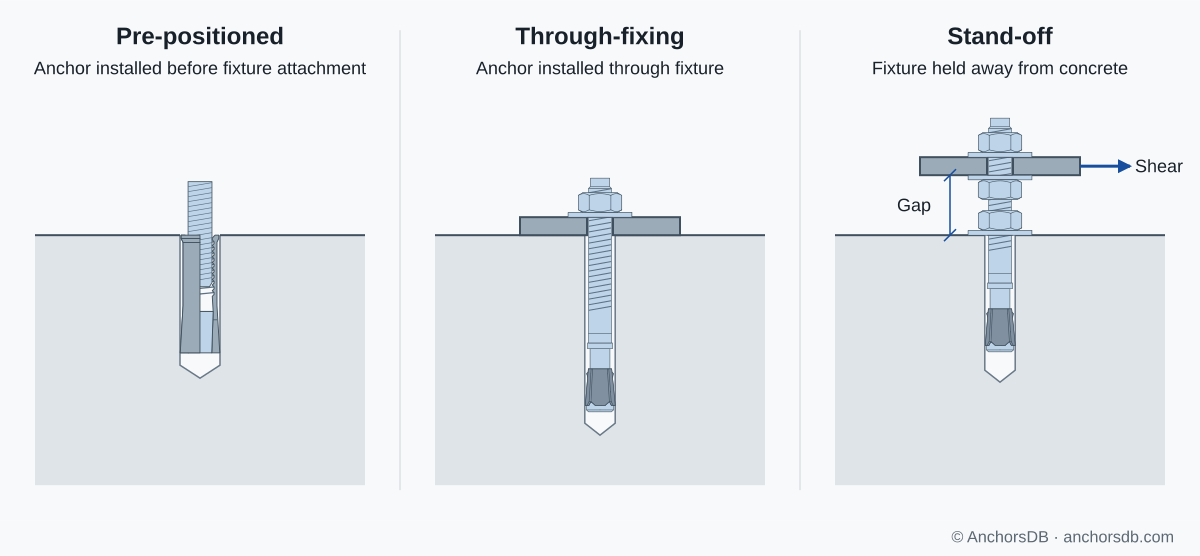
Figure 1. Anchor installation arrangements.
Pre-positioned installation
The hole is drilled and the anchor is set before the fixture is placed. The fixture is then positioned over the anchor and secured with a nut or bolt. A drop-in anchor, for example, is set flush with the concrete surface and receives a threaded rod for a pipe hanger; a bonded threaded rod is installed and cured before a baseplate is placed over it.
The clearance hole in the fixture only has to pass the bolt or rod, so it can be smaller than the drilled hole in the concrete. Deviations in anchor position must fall within the clearance between the bolt or rod and the fixture hole. Only the bolt or rod crosses the joint between fixture and concrete, so it carries the shear alone.
Through-fixing installation
In through-fixing, the anchor is inserted through the fixture into the drilled hole and set with the fixture in position. The hole positions are taken from the fixture: the concrete is drilled through the fixture holes, or the positions are marked through them and the fixture is removed for drilling and then replaced. The anchors therefore match the fixture holes, which suits plates with several anchors.
The clearance hole must pass the anchor, and also the drill bit where the concrete is drilled through the fixture. For shear loading, EN 1992-4 covers only fastenings without hole clearance or with clearance holes not exceeding the values in its Table 6.1, for example 12 mm for a 10 mm fastener and 18 mm for a 16 mm fastener; where a sleeve bears against the fixture, the sleeve diameter is the reference. The European Technical Assessment (ETA) gives the clearance-hole diameter for each anchor size.
A sleeve anchor installed through the fixture has its sleeve in the fixture hole, where the sleeve contributes to shear resistance. In tests on undercut anchors with 16 mm bolts, this arrangement gave significantly higher shear failure loads and displacements than pre-positioned installation with the bolt alone resisting shear.
Anchor length and intervening layers
In pre-positioned and through-fixing installations, the usable fixing length of the anchor must be at least the fixture thickness. A non-load-bearing layer between the fixture and the structural concrete, such as plaster, screed or insulation, adds to the required length, and the embedment is measured from the surface of the load-bearing concrete. The ETA gives the maximum fixture thickness for each anchor length and embedment. Except for a thin levelling mortar meeting the conditions of EN 1992-4, such a layer also causes shear to act with lever arm; see tension, shear and combined loading.
Stand-off installation
In a stand-off installation the fixture is held at a distance from the concrete surface, typically on levelling nuts, as for a levelled column baseplate or a façade bracket. The anchor spans the gap and transfers both tension and compression into the concrete. A post-installed mechanical anchor requires a bearing washer and nut at the concrete surface to transfer compression; the same detail is recommended for bonded anchors. Under alternating loads, the anchors carry alternating tension and compression; with a fixture bearing on the concrete, the compression would pass by contact and the anchors would carry pulsating tension only.
Shear on the fixture bends the anchor across the gap. In EN 1992-4, the lever arm extends from the line of the shear load to a point half the anchor diameter below the concrete surface, or to the surface where a washer and nut are clamped to the concrete. The design bending moment is the shear force multiplied by the lever arm, halved where the fixture fully restrains the anchor against rotation. Bending considerably reduces the shear resistance of the anchor steel. Near an edge, the moment from the gap also adds a shear component towards the edge and reduces the concrete edge resistance. The ETA gives the characteristic bending resistance of the anchor steel used in this verification.
For the drilling that follows, see drilling methods for post-installed anchors. Hole clearance and shear distribution in groups are explained in how an anchor group shares load.