

During an earthquake, the structure accelerates and every attached component develops inertial forces that its fastening must transfer. At the same time, the concrete around the anchors cracks, and the cracks open and close as the structure deforms. EN 1992-4 covers anchors that transfer seismic actions between structural members (Type A connections) and between non-structural elements and the structure (Type B connections). Only anchors whose European Technical Assessment (ETA) covers cracked concrete and seismic use may be used.
Inertial forces on attached components
A component fixed to a floor or wall is accelerated with it and resists that acceleration with an inertial force equal to its mass multiplied by the acceleration. The acceleration at the component's support increases with its height in the building, and is amplified further when the component's natural period is close to that of the building. EN 1998-1 gives the horizontal force on a non-structural element from its weight, its height in the building, its importance and a behaviour factor; EN 1992-4 supplements this with amplification factors for common elements, such as 3.0 for electrical and communication equipment and 1.5 for partitions and façades.
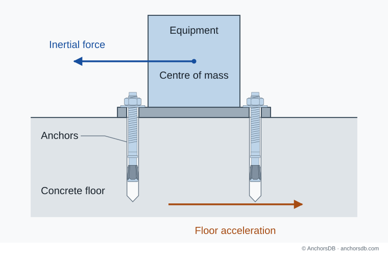
Figure 1. Floor acceleration and the inertial force on anchored equipment at one instant.
Forces in the equipment connection
The inertial force acts at the centre of mass, above the concrete surface. It is transferred to the anchors as shear and, because of its height, as an overturning moment. The moment produces tension in the anchors on one side and compression under the baseplate on the other. The taller the component relative to its anchor spacing, the larger the tension. The direction reverses during the earthquake, so each side of the base is alternately in tension and compression, and the vertical component of the ground motion adds to or reduces the effect of the self-weight. The distribution to the individual anchors follows how an anchor group shares load, provided the baseplate remains elastic. Supports connected to different parts of a structure must also accommodate the relative displacement between them.
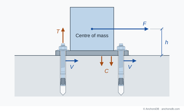
Figure 2. Forces in an equipment connection at one instant.
Cracking and load reversal
The concrete around the anchors is taken as cracked in seismic design, unless it is shown to remain uncracked during the earthquake. Cracks passing through the anchor location open and close with the response of the structure, while the tension in the anchor pulses and the shear changes direction. An opening crack reduces the expansion or bond contact of a post-installed anchor, and repeated cycling can increase its displacement and reduce its resistance. Where the fixture has hole clearance, the reversing shear makes the fixture strike the anchor at each reversal, which raises the anchor forces.
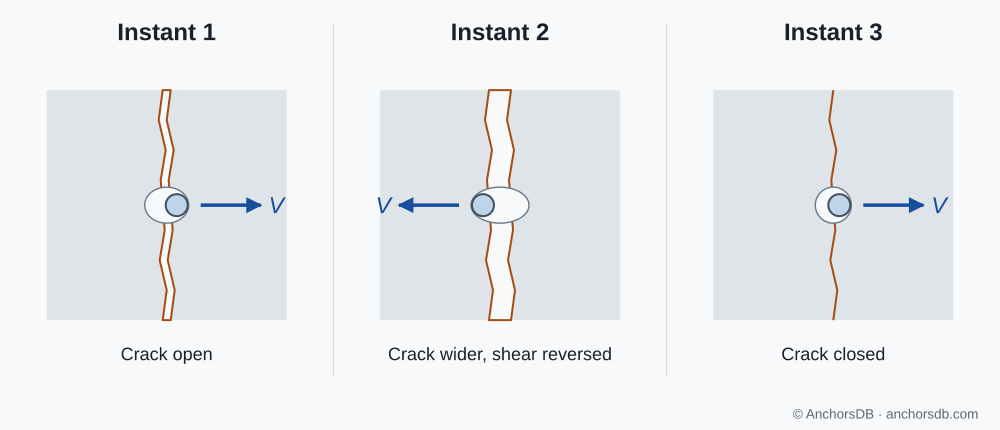
Figure 3. Crack width and shear direction at three instants. Crack widths are exaggerated.
Seismic performance categories C1 and C2
The ETA states the seismic performance category of the anchor and gives its seismic resistances for steel failure, pull-out and bond, determined in tests with cyclic loads in cracked concrete.
| Category | Data in the ETA | Typical application recommended by EN 1992-4 |
|---|---|---|
| C1 | Seismic resistances at the ultimate limit state | Buildings of importance class I; non-structural elements in importance classes II and III at low seismicity |
| C2 | Seismic resistances and displacements at the damage limitation and ultimate limit states | Importance classes II to IV above low seismicity; at low seismicity, structural connections in importance classes II and III and all connections in importance class IV |
C1 tests apply pulsating tension and alternating shear in cracks 0.5 mm wide. C2 tests use cracks up to 0.8 mm wide and add tension tests in which the crack is repeatedly opened and closed; the C2 programme includes the C1 load types, so an anchor qualified for C2 is generally used for C1 applications as well. The recommended assignment depends on the seismicity level and the importance class of the building to EN 1998-1, and the National Annex may change it. In regions of very low seismicity, fastenings may be designed as for non-seismic loading.
Seismic design to EN 1992-4
EN 1992-4 treats anchors as elements that do not dissipate energy and offers three design options:
- Capacity design: the anchors are designed for the maximum force that a ductile yielding element, such as the attached steel member or the baseplate, can transmit, including strain hardening and overstrength.
- Elastic design: the anchors are designed for the seismic forces calculated without reduction for ductility, with an additional amplification of 1.5 when the simplified method for non-structural elements is used.
- Ductile anchor design: for tension only, with a C2 anchor whose steel fails before the concrete and which has sufficient elongation capacity; this option is not used for primary seismic members.
Seismic resistances are lower than static ones. The resistances for concrete failure modes are calculated as for static loading and reduced by a factor between 0.75 and 1.0, depending on the failure mode and on whether the anchor acts alone or in a group; for groups, a factor of 0.85 also applies to the ETA seismic resistances for pull-out, bond and steel failure in shear. An annular gap should generally be avoided. It is allowed only for non-structural elements in minor non-critical applications, where it halves the shear resistance unless the ETA gives another value. The nut must be secured against loosening, and displacement must be limited where the connection is assumed rigid or the equipment must remain operational. Stand-off installations, grout layers of half the anchor diameter or more, anchors qualified only for redundant non-structural systems, and plastic hinge zones of concrete members are outside the scope of the method.
For the concrete condition in ordinary design, see cracked and uncracked concrete; for displacement limits, see anchor displacement and connection stiffness.